Photonic testing requires both equipment that creates a known optical condition and a system that measures the device response with defensible uncertainty. They treat these roles as one workflow. A high-speed stimulus is not useful if its bias drifts, and a precise receiver cannot produce credible data when source power, wavelength, or modulation state remains uncontrolled.
The chain usually includes a laser, modulator, RF drive, attenuation, monitoring, device fixture, detector, analysis, and software. Each interface can add loss, reflection, noise, or variability.
They define reference planes and responsibility for every element, then verify the chain with standards and control devices before using it for product qualification or production screening.
Workflow diagrams identify where each quantity is generated, monitored, corrected, and recorded, helping reviewers detect gaps or double counting in the uncertainty analysis. For the combined workflow, current fiber optic test equipment combines an EO transmitter, automated bias control, and a narrow-linewidth source.
They use these building blocks to create repeatable conditions for high-speed communication, coherent measurements, chirped sensing, and device characterization, while adding the detectors, fixtures, environmental control, and traceability required by each application.
Signal Generation Establishes a Controlled Optical Stimulus
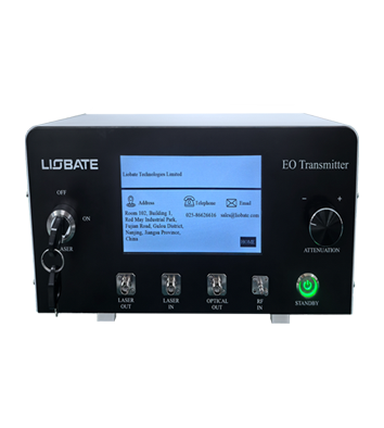
Fiber optic test equipment begins the workflow by generating a controlled optical stimulus. An EO transmitter available at 40, 70, or 110 GHz can create high-speed modulation while integrating a DFB source, monitors, attenuation, and bias control.
They select the bandwidth from the waveform spectrum and the margin required by the device under test. At the device reference plane, optical measurement systems must characterize the stimulus presented to the device. They measure optical power, wavelength, polarization, RF response, and modulation state, then record settings and correction files.
Integrated monitors are useful, but their calibration and location must be understood so that internal readings can be related to external standards and fixtures. Attenuation supports receiver sensitivity, linearity, and dynamic-range tests when it is calibrated across wavelength and power.
They verify repeatability after changes and include connector loss. Automated sequences sweep controlled levels while capturing the response. The resulting curves provide more information than one pass/fail point and reveal compression, noise floor, or unstable transitions.
Stabilization and Monitoring Protect the Measurement Reference
An automatic controller keeps an intensity modulator near its chosen bias, helping fiber optic test equipment produce stable output during long sequences. They log the correction voltage, lock state, residual drift, and recovery after interruption. Stable output without control history can conceal a device that requires increasing compensation or is approaching the controller range limit.
For coherent and sensing work, optical measurement systems may use a narrow-linewidth laser. The listed source operates at 1551.4 nm with 8 dBm output, intrinsic linewidth of 200 Hz or less, chirp bandwidth above 8.2 GHz, and linearity above 0.9993.
They verify these properties in the relevant sweep and timing mode. Monitoring protects the reference by identifying source drift, thermal movement, connector contamination, or polarization change. They define alarm and recalibration thresholds from measurement sensitivity. Environmental sensors and control samples provide additional context.
When a result changes, these records help them determine whether to investigate the device, fixture, source, controller, or receiver. They test the chain with known attenuation, frequency, and bias disturbances, confirming that alarms and analysis routines respond with the expected sensitivity and direction.
Integration, Calibration, and Data Management Complete the Workflow
Integration of fiber optic test equipment can reduce setup time and connection variability, but it should not remove access needed for calibration or troubleshooting. They review internal reference points, remote commands, timing, replaceable modules, and data export.
A compact system is useful when it creates a simpler controlled chain, not when it makes uncertainty impossible to allocate. Across the full station, optical measurement systems require a calibration hierarchy covering power, wavelength, RF response, timebase, attenuation, and detector linearity.
They schedule formal calibration and intermediate checks, then use reference devices to detect drift. Correlation across stations and laboratories establishes whether results can be combined for supplier decisions, design limits, or manufacturing release. Data management closes the workflow.
Every result includes unit identity, station, fixture, configuration, firmware, calibration state, environmental conditions, and software version. Raw data is retained where reanalysis may be needed. Automated reports summarize the decision without replacing underlying evidence, allowing audits and failure analysis to reconstruct exactly how a measurement was produced.
Ownership of reference standards and software repositories is documented, preserving continuity when laboratories, suppliers, or production sites change during the product lifecycle. Test equipment and measurement systems work together when signal generation, stabilization, observation, calibration, and analysis are designed as one traceable process.
A stable source and modulator create the condition; monitors and controls preserve it; detectors and software quantify the response. Weakness in any element limits the confidence of the final result.
Their implementation begins with the test objective and uncertainty target, then assigns specifications and controls to each part of the chain. Capability studies, station correlation, automation challenges, and support planning verify that the workflow can survive operator changes, long test runs, equipment maintenance, and transfer from development into routine manufacturing.
Signal generation, monitoring, detection, calibration, automation, and data governance have to form one controlled measurement chain. Placing Liobate components inside that chain shows how they affect correlation, uncertainty, throughput, and maintenance in day-to-day use.